API TR 1152:2013 pdf free download.Industry Recommended Subsea Dispersant Monitoring Plan Version 1.0
1 Images collected from video cameras on the ROV before and during injection are used to determine if the color of the visible oil cloud is changing, which indicates the oil is being dispersed.
2 The ROV will be raised upwards through the water column keeping a constant distance from the cloud. The video images will be used to detect changes in the cloud density and shape as the oil, gas, and dispersant mixture rises through the water column and is dispersed by local currents. Aerial Monitoring
1. Aerial monitoring will be conducted before and during the application of the dispersant to determine if the use of dispersant is reducing the amount of oil reaching the surface 1
2. Flights will be conducted before and during the application of dispersant. These flights will occur only after sufficient time has elapsed to allow oil to fully express on the surface. Depending on the water depth, this could require several hours. Flights before dispersant application must allow sufficient time for untreated oil to reach the surface after initiation of the well-control event. Flights during dispersant application must allow time for the water column to clear of untreated oil and the surface slicks to transfer out of the observation area. Observations will be documented using visual assessments by trained observers and documented using photographic resources. Aerial monitoring efforts must take into account local currents that can potentially transport the rising oil (dispersed or not) some distance from the spill site, depending on the strength, depth, and direction of the currents. VOC and %LEL Monitoring
1. VOC and %LEL monitoring equipment and trained users will be stationed on vessels located near the well site. Significant reductions in VOCs will indicate a reduction in fresh oil slicks near the well site. As with aerial monitoring, efforts must take to account local currents that can transport the rising oil (dispersed or not) some distance from the spill site and local wind direction that can transport VOCs away from surface vessels. VOC and %LEL measurement will be affected by surface conditions such as wind speed/direction and location of the monitoring device relative to the surface slick location. For example, vessels upwind of surface slicks could have low VOCs and %LEL even with surface slicks nearby. These additional variables could complicate interpretation of the VOC and %LEL data. These complications may limit the ability to draw definitive conclusions on the effectiveness of subsea dispersants from this data. Weather conditions should be reported along with all VOC data. Corresponding representative water samples should be collected and analyzed for individual constituents. A diagram should be prepared identifying the time and location of all VOC samples taken. VOC and %LEL data should also be provided to the FOSC, and the UC Safety Officer for gauging potential threats to workers.
2. Workers will be equipped with exposure badges to monitor Permissible Exposure Levels (PELs) to VOCs per OSHA standards. The resulting data should be reported to the IC, the DEMU, and the Safety Officer.
• Ship-based VOC and %LEL monitoring instruments with trained operators
• Worker detection badges for PEL monitoring
• Two ROV’s equipped with video cameras – one for dispersant application and one to monitor dispersant effectiveness
• Trained ROV operators
• Trained observers in the ROV control room and on the aerial platform with an approved field guide and camera
• Aerial platform – aircraft (either fixed-wing or helicopter) with appropriate communication and Global Positioning System (GPS) navigation suit
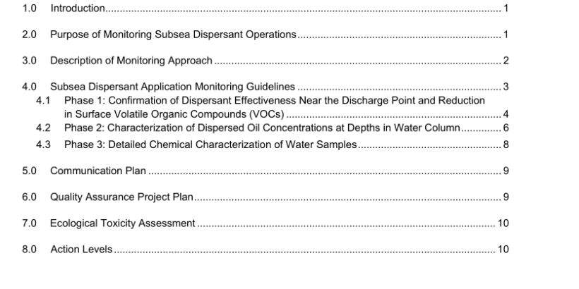
4.2 Phase 2: Characterization of Dispersed Oil Concentrations at Depths in Water Column
Description of Operation
Water column monitoring seeks to determine the location, extent, and characterization of the dispersed oil plume at depth. The extent of such monitoring increases with the length and volume of the release. Local oceanographic data together with hydrodynamic models, if available, will determine the likely direction of movement of the sub-surface oil.API TR 1152 pdf download.API TR 1152:2013 pdf free download
