API MPMS 7.3:2011 pdf free download.Manual of Petroleum Measurement Standards Chapter 7.3 Temperature Determination—Fixed Automatic Tank Temperature Systems
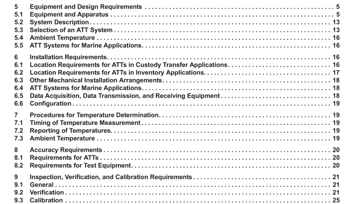
5.1.3.2 Multiple-Spot (Averaging) ATT Multiple-spot temperature sensors are installed (or encased in a flexible element housing) at approximate 2 m to 3 m (6 ft to 10 ft) intervals with the lowest sensor approximately 1 m (3 ft) from the bottom of the tank. Typically, all temperatures for an ATT element are measured by a single transmitter. The ATT transmitter may be an integral part of an ATG system which has computing ability to provide a tank temperature profile and/or an average temperature (based on the submerged sensors), or in some cases, the averaging function may be performed by the ATT transmitter/system.
A typical multiple-spot temperature sensor installation is shown in Figure 1. Where the tank is operated at a level lower than 1 m (3 ft), an extra temperature sensor can be located at a level as low as practical so as to have a submerged sensor when the tank is operated in this range. This sensor should not be averaged with the other ATT sensors when the tank is operated at or above 1 m (3 ft) to avoid a misrepresentative average caused by ambient ground temperature effects.
5.1.3.3 Variable-Length ATT A number of RTDs of varying lengths, all of which extend from the bottom of the tank, are encased in a flexible sheath. Only the longest, fully submerged RTD is used to determine the average temperature of the liquid in the tank. The correct RTD is typically selected either by a switching device in an ATT or ATG transmitter or by software elsewhere in the system (typically human-machine interface (HMI) computer). Because of the use of a bottom mounting bracket and/or anchor weight, the sensitive portion of the element begins at some level above tank bottom, typically 0.15 m (6 in.), so that the lowest 0.15 m (0.5 ft) in the tank is not measured. Anchor design should consider typical free water and tank deposits levels. The sensitive portion of the element should provide a representative temperature for the liquid and may have to be positioned 1 m (3 ft) from the tank bottom or above the low point of the tank outlet. A typical variable-length ATT temperature element installation is shown in Figure 2, and an example of sensor lengths given in Table 2.
5.1.4 Multiple-Spot (Non-averaging) ATT Multiple-spot ATTs may be provided with individual spot sensors without an averaging function. Otherwise the design and construction is similar to an averaging ATT as described in 5.1.3.2.
5.1.5 Protecting
Tube A protecting tube is used for some ATTs for mechanical protection and to ensure positional stability of the temperature sensor(s) within the tank. It provides the same functionality for an ATT as an armored case does for a liquid-in-glass thermometer. For multiple-spot and variable-length ATTs, the protecting tube shall have holes or slots to ensure that the product in the protecting tube is representative for the product level and temperature in the tank. Various designs of vertical protecting tubes are available to support multiple-spot or variable-length ATT temperature sensors in floating-roof or fixed-roof tanks.
5.1.6 Thermowells The use of thermowells may be required to isolate the liquid material from the temperature sensor or to provide mechanical protection. They may be inserted through the tank wall, horizontally or at an angle, or through the tank roof vertically. Thermowells may be filled with a heat transfer medium to ensure the temperature sensor accurately reflects the tank temperature. Pastes or fluids may be used depending on the orientation of the thermowell. Thermowell design should allow for thermal expansion of the medium. Adequate clearance should be provided between the ATT sensor assembly and the thermowell for ease of insertion. The clearance, however, should be kept as small as practical to reduce the time lag for heat transfer. Thermowells used to allow the insertion of a reference thermometer for the purposes of verifying the accuracy of the ATT are referred to as test thermowells. Test thermowells should be capped when not in use to prevent foreign material from accumulating in the bore. A clogged thermowell may cause measurement errors and may damage thermometers.API MPMS 7.3 pdf download.API MPMS 7.3:2011 pdf free download